Target Carrier and Frame Plans
by Edwin C. Hall
Back to Homepage
Although not tested, here are some suggested plans I came up with for building the supporting structure and frames for a turning target system. These are very basic plans and don't include all the details. It will be up to the builder to calculate any dimensions needed, such as target frame width, separation and crank arm length. The latter will need to be determined from the travel distance of the actuating device. I have also left off that device instead of suggesting one. The actuator can be a solenoid, motor or air cylinder, as referenced in my other plans, or possibly something entirely different. Having not built anything from these plans, I have no idea how much force is needed to turn different numbers of targets, but the plans describe only one target and will need to be duplicated, etc. for the additional positions. The system can be mounted with the frame(s) pointing up or down depending on the user's needs. I've suggested small mounting holes in the front edge of the box tubing to be used for fastening the tube to a structure, possibly a 4x4, with larger access holes in the back edge so the fasteners can be reached. After each of the pictures, I have added some notes. Also, the pictures can be selected to bring up slightly larger versions.

- Use 1" x 2" box tubing, cut to the length needed for the number of targets desired. If necessary, build bays of targets that can be connected together. This can allow for storage of portable bays of targets.
- Use ball bearings with a flange. This allows for mounting the bearings into the steel tube and allows for a very rigid mounting of the frame to the bearings.
- Be sure to use appropriate spacers (washers will work) between the bearings, so that when you tighten the carriage bolt you don't stress the bearing. It may be necessary to mount one bearing and hold the spacer in place while you mount the other bearing and then feed the frame assembly carriage bolt through the bearings. Alternately, you might be able to cut an access port in the edge of the tubing, but that may be a bit of extra work.
- In the top view, the heads of the mounting bolts can be seen. These allow the box tubing to be mounted to a structure that can protect, as well as support, the carrier. Be sure to allow ample clearance for the turning frame.
- Be sure to make the right size hole for the mounting portion of the bearing OD, not the flange size.

- If you tap the cross bar ends and mount the rods with top lock nuts as shown, you can eliminate the need for nuts on the bottom that could catch the connecting rod.
- If possible, for the carriage bolt hole through the cross bar, make it square shaped to mate with the square shoulder under the carriage bolt head. This will keep the bolt and cross bar locked together - not entirely necessary, but better in this application.
- Be sure to pin the crank arm to the cross bar with spring pins so it remains in its proper orientation of 45 degrees from the bar.
- In the picture, 1/8" x 1" bar steel is suggested for the connecting rod. Angle steel could be used if more strength is needed due to long runs between targets.
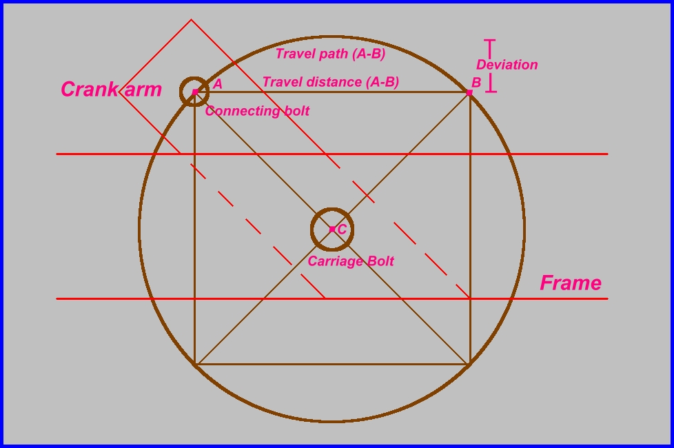
- The crank arm connection point determines the travel needed to turn the target 90 degrees. To calculate this distance for an actuator with a known throw, you can think of the geometry of an isosceles right triangle with the hypotenuse as the travel distance. (Truly, the connecting point will move in a 90 degree arc, but will start and stop at points relative to two adjacent corners of a square centered on the target turning point.
It sounds like a lot of confusing math, but a calculator with square root capability should be able to provide an answer using the following procedure:
Let's start with something simple. We'll consider the actuator we're using to have four inches of travel, as with some air cylinders. That four inches will become our A to B measurement. Let's even add in a diagram:

- 1. Enter 4 * 4 = and receive 16 for the first answer.
- 2. Divide 16 by 2 and receive 8 for the second answer.
- 3. Find the square root of 8 and receive a number with a long fraction, 2.828427...
- This value is the distance from the center of the carriage bolt to the center of the connecting bolt (A-C). I would round this dimension down so there is a little more, rather than a little less rotation of the target. In fact, if using an air cylinder, it might be more advantageous to make the travel considerably less and use bumper stops to align face and edge positions.
- Another thing to note is that in traveling through the arc, the connecting bar will move further from the target turning point (and mounting structure - 1" x 2" tubing) and then back. You should allow for this deviation when you consider the mounting of your actuator. To calculate this deviation, subtract half of the travel distance from the value obtained in step 3 above. For our example, that gives us a deviation of 2.828427 - 2 = .828427 inches.
There are many details left for the builder to figure out, but I hope this helps in allowing more ranges to come up with inexpensive systems for their turning target needs. I will review and possibly add more material as time permits.


