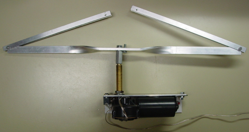
Since a new motor has appeared on the scene, I have redesigned once again, to what I am now calling the "Model 2013." This latest design is similar to the previous ones, with only changes driven by the different construction of the new motor. Again, this new motor has a parking position, making the circuitry simple, but this time, the arm oscillates, so for this design we only need to break the motor signal at the proper place to create a turner that faces and edges. That work is described in the next few paragraphs. The unit is still powered by a 12 volt, 4 (or 5) AH, sealed lead acid rechargeable battery which will last for several hours of use.
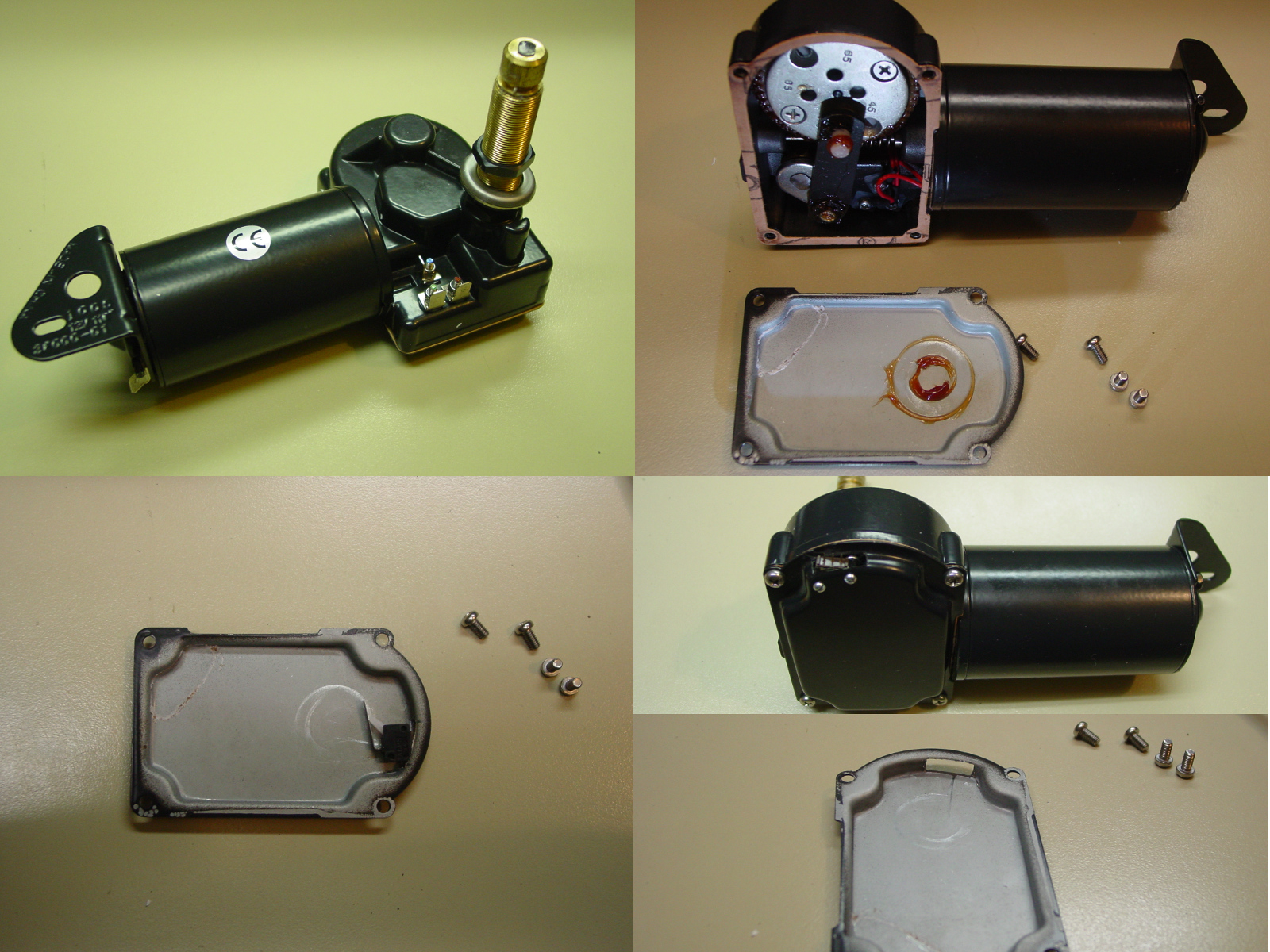
The heart of the turning system is again a windshield wiper motor. This new motor is made by Marinco. The model I'm using for this page is #38000-01, which means it is 12VDC, with a 2.5 inch shaft and four spade connectors. This particular motor comes in several other styles to include a rocker switch and various length shafts. (The motor shown at the top right of this page is actually #38005-01, with a 3.5" shaft, but the remainder of the page is described using the 38000-01 motor.) Currently, the best pricing for this motor is from Surplus Center.
As with previous designs, this target system is also built to be faced by a short circuit contact device such as a switch or relay and edged when the short is removed.
Currently, I have only built one of these with the new design, but decided to place this information into the public domain now rather than waiting for more experience with building them using this document. So, this iteration hasn't been tested as much as earlier ones. I'd appreciate any feedback on how this has worked for others. Feedback can be provided on either the Bullseye-L list or forum, or by other common methods. If I can provide a means for someone to afford a turning system, then I'm happy to have published these pages. If help or more information is needed, contact me (15 Lakeview Ave, Tupper Lake, NY 12986).
A list of materials I use is at the end along with limited source information. Many of the parts are common type items found at many hardware stores, but some are from other places, such as electronics surplus, etc.
Of course, no printed instructions can be free of a safety reminder these days. Due to the inability of me to be by your side through this, you will need to assume all risk involved with the construction and/or use of this system. This includes, but is not limited to, the use of all tools involved. Additionally, this system has moving parts! Be aware of the pinch points and swing position of the frame when using it. The battery should only be connected while you are out of reach of the turning parts. Disconnect the battery at any time you are within the swing radius.
Feel free to provide feedback on how this project has worked. I will try to change it if better parts appear or techniques evolve. I have reviewed this document countless times, but there is no guarantee of accuracy. If an error is found, I will attempt to make necessary corrections in an expedient manner. Please feel free to send me comments.
The first thing to do is to turn the motor upside down and remove the four screws that secure the bottom plate. Carefully remove the plate, trying to preserve the gasket. Check to make sure the white pin is in the hole marked "110." If it isn't, follow the motor instructions to move it to the "110" position, replace the cover, connect a battery to the motor and let it run for a few cycles, then remove the cover again. Look at the inside surface of the plate and note the path of the plastic pin, which has left its circle in the grease. Scratch or mark the outer edge of the circle nearest the curved end of the plate and then remove the grease. Now try to find the proper placement of the switch, such that the lever will be depressed by the pin when its arc is centered in the curved section of the plate, as shown in the pictures. Make note of the area of the plate that will need to be removed to provide clearance for the switch. In my case the switch is thin enough to allow the lip of the plate to be left in place. The switch you use may not be this slim, so if necessary, remove the lip as well. Drill the holes for the switch and mount it into place. Place the plate back onto the bottom of the motor and secure it with its four screws.
Next, the end of the shaft will need to be turned down somewhat and threaded to accept the larger end of a 1/2"-13 to 3/8"-16 adapter. This doesn't need to be done in a precise manner, but the more even the trim, the better the result. I use a grinding wheel to take off some material around the perimeter. Only remove what is needed to give the die a good dimension to work with. Then, carefully square up the 1/2"-13 die and thread the end of the shaft. Note that the lower portion of the brass cap will crumble away. This is expected, but should leave a sufficient amount to affix the coupler. Do not permanently install the coupler at this time.
Now let's cut a piece of 1/8 inch thick 2" x 2" angle aluminum to 8.5 inches long. See the image for the orientation and dimensions to use to drill the holes. Drill the 5/8" hole for the shaft, 1.5" from the end and 3/4" from the open edge. Place the shaft through the hole to check the fit. If the fit is correct, mark and drill the hole for the mounting tab at the base end of the motor. I drilled appropriately for and used a 6mm bolt and nut, because I had some handy. While you're working on the bracket, drill an appropriate hole for the 1/4" jack. For mine, I drill the hole 1/4" in from the end of the angle aluminum and spaced to allow the relay to fit between the jack and the back side of the bracket.
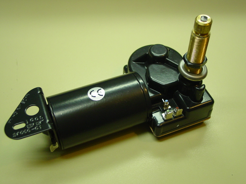
First, let's look at all the connections we'll be using. In the picture of the motor, there is a ground terminal at the lower left, underneath the mounting tab. This will be connected to the negative terminal of the battery and one terminal (preferably the sleeve) of the 1/4" jack. Second, find the blue post on the motor. This is the park terminal and will be connected to the Normally Closed (NC) pin on the relay. Third, find the red post on the motor. This will be connected to the new switch in the base cover. The green post on the motor is the low speed connection and will not be used in this procedure. Let's move back to the connection for the new switch installed in the base cover. As noted, one terminal will be connected to the red post. This needs to be either the (C)ommon or the NC pin and the other of the two will be connected to the Normally Open (NO) pin on the relay. The NO pin (if present) on the switch will not be used. The next connection described is between the tip connector of the 1/4" jack and a coil pin on the relay. The last connection is the positive terminal of the battery, which will be connected to the Common (C) pin of the relay and to the opposite coil pin from the one referenced in the previous sentence.
Let's actually step through the wiring. (You can remove a short section of the speaker cable to perform these connections.):
The motor should now work appropriately. However, it is critical that you do not connect the battery backwards, or depending on the positioning of the new switch in the base, it could be destroyed by the motor turning in reverse. So, be cautious connecting the battery to the turner. The motor may or may not do anything, since it might already be parked. Provide a short across the 1/4" jack connections. The shaft should turn approximately 90 degrees. This will not be exact and the shaft may move slightly back toward edge before stopping, but if it stops at about 90 degrees, it is working. Remove the short from the 1/4" jack. The shaft should return to the parked position. Test this operation a few times to see if it is working properly. If the face postion is too early or late, as evidenced by an exagerated bounce either before or after the face position, the switch will need to be moved. If a minor movement is necessary, I suggest you make the original screw holes into slots. If a gross adjustment is needed, new holes should be used.
Once the proper operation of the motor has been confirmed, it is time to put it all together. First, tighten the bottom shaft nut to the motor housing. Next place the shaft through the bracket and add the rubber grommet, the decorative washer and the top nut, in that order. Finger tighten the top nut onto the decorative washer. Second, install the bolt and nut through the mounting tab and bracket, using lock washers, if desired. Third, mount the 1/4" jack into its hole. Using hot glue or silicone sealant, mount the relay. Using hot glue or silicone sealant, seal the hole around the switch mounted in the base plate of the motor. Snug all the fasteners.
The motor should still be in the park position from earlier testing, so it's time to affix the adapter. Clean the mating threads with acetone (or similar), apply either an Epoxy or J.B. Weld to the initial threads of the 1/2"-13 end of the adapter and screw it onto the shaft far enough to engage all the shaft threads, but not far enough to get any adhesive into the shaft core. Align two (opposite, of course) flat faces of the adapter with the long edges of the bracket. Set the assembly aside to allow for all the adhesives/sealants to cure.
Note: You will need to determine the polarity of the connection based on the polarity of your charging system's coax connector!
Note: Several drill bits will be determined by the size of the fasteners and such that you are using. Additionally, several parts will depend on each other, such as the battery connector will be determined by the charger connector, which will, in turn, drive your choice for the turner connector. This list will be inclusive of all tools and parts and roughly presented in the same order as used above.
